Pulse Dialing Detection
Pulse dialing was the standard method of digit signaling in rotary telephone systems from the early 1900s through the 1980s. Each digit was transmitted as a series of timed loop break pulses, created by rapidly toggling the telephone’s internal switch hook contacts as the dial rotated back to rest.
Overview
Each digit generates a specific number of pulses:
Digit “1” = 1 pulse
Digit “2” = 2 pulses
…
Digit “0” = 10 pulses
Each pulse consists of:
Break (on-hook): ~60–70 ms (open loop)
Make (off-hook): ~40 ms (closed loop)
A ~700–800 ms pause after all pulses marks the end of the digit
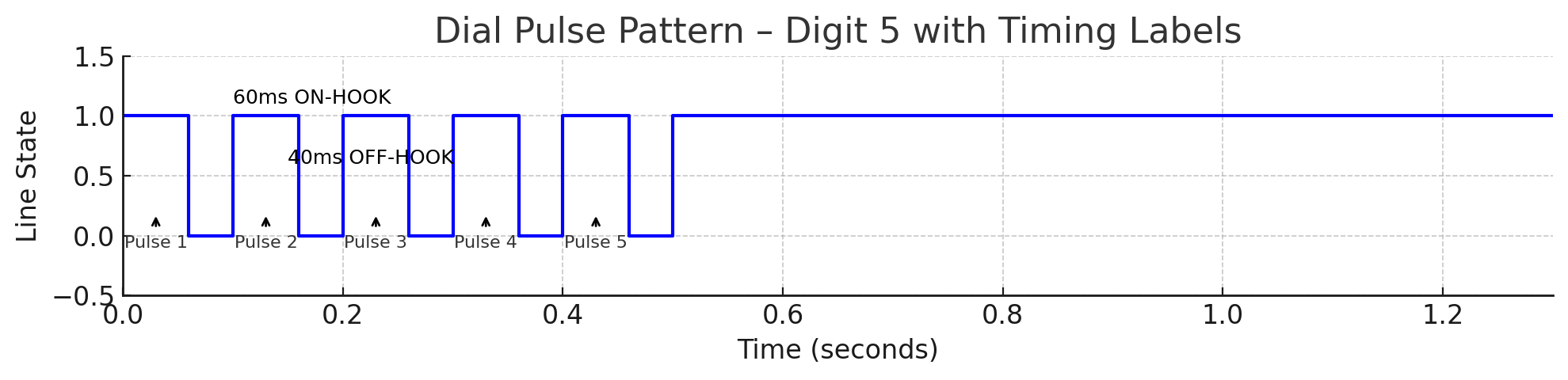
Pulse Dialing – Digit 5: Five loop break pulses, each ~60 ms open and ~40 ms closed, followed by a post-digit pause.
Note
Why does “0” send 10 pulses? This legacy behavior comes from early switchgear that had no concept of “digit zero.” The switch simply counted pulses, so “0” was encoded as the maximum—10 pulses—and positioned last on the rotary dial.
Historical Evolution
1900s–1940s: Step-by-step switches and rotary selectors mechanically counted loop breaks.
1950s–1970s: Electromechanical relays and early transistor circuits refined accuracy and reduced noise.
1980s–2000s: Modems and fax machines began using microcontrollers to decode rotary pulses.
Present: Embedded systems and GPIO edge detection provide precise, software-based pulse decoding.
Anti-Tinkle Suppression
One challenge with pulse dialing was the “tinkle” sound — faint bell rings caused by pulse transitions during dialing. This occurred when the ringer briefly saw inductive spikes from loop current changes.
To suppress tinkle:
CO equipment muted the ringer path during dialing
Some phones included anti-tinkle circuits using rectifiers or spark gaps
Advanced PBX gear actively blocked ringers during loop break sequences
Detection Requirements
Any pulse detection circuit must:
Observe rapid transitions (10–15 pulses per second)
Count accurately, even with contact bounce
Distinguish digits via pause detection
Remain isolated from -48V DC line voltage
Detection Options
Option 1: Software-Based Detection (Modern Embedded Style)
Monitor loop status via GPIO or interrupt
Measure transitions and timing in firmware
Debounce and group pulses into digits
✅ Simple and flexible ✅ No extra hardware ❌ Requires reliable software timing
—
Option 2: Dual-Path Detection
Split the signal from the off-hook circuit: - One path with filtering for steady-state hook detection - One fast path for raw edge detection (via Schmitt trigger or comparator)
✅ Preserves clean edges ✅ Reduces false detection ❌ Slightly more complex circuit
—
Option 3: Dedicated Pulse Decoder Circuit (Historical/Nostalgic)
Use analog building blocks: - Monostable 555 timers - RC differentiators and comparators - Custom relay-based pulse counters
✅ Vintage authenticity ❌ Bulky and obsolete ❌ Less flexible than software
Summary
Rotary dialing encodes digits as timed loop break pulses
Reliable detection requires clean edge sensing, debouncing, and pause tracking
Options include pure software, hybrid circuits, or dedicated analog logic
Pulse dialing remains an essential compatibility feature in vintage phone systems